Page 5 of 7 FirstFirst ... 34567 LastLast
Results 81 to 100 of 140

Thread: Titus's V6 Swap build thread

  1. #81

    Default

    Thanks!

  2. #82

    Default

    Great progress, good luck on the soldering, it can be tricky but seeing as you have a nice temp controlled iron, it will make things much easier.

    If you want, here is some reading on NASA spec wiring.It covers all aspects of splicing, bundling, soldering, etc. with pictures of right and wrong.
    '06 RSX Type-S NBP

  3. #83

    Default

    Dang is right...........my head hurts even thinking about the wiring much less attempting to do it. Hopefully your fruits will pay off when that thing busts off at the first turn of the key.

  4. #84

    Default

    The Water Passage. This is going to be a long post.... On the back of the J series motor, there is a coolant manifold that Honda refers to as the water passage. Water coming out from the water pump passes through one middle of the water passage, through the thermostat, and out to the radiator, and then it comes back in to another section of the manifold from the radiator return where it is routed in to the back of each head. It also contains EGR passages that run from the head to Intake, the EGR valve mounts to it, The Air-Assist valve is mounted to it, it holds a temp sensor, and it has misc coolant input/output connections for Heater core, transmission cooler, and IAC valve.


    This is what a stock one looks like off the motor (not mine)


    While not really mandatory, there are several things that I am changing about my water passage. First was the replacement of the EGR valve with a blockoff plate. (This was shown back near the beginning, but here it is again to show all related things together:


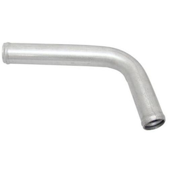
    The second change relates to the big coolant return pipe seen in the top right of the stock part photo. It is pointed back toward the firewall. While there is clearance between the firewall and pipe itself, it doesn't really leave the room needed to get a hose on there. Given that the Minitech kit is budget minded, the instructions call for you to "massage" the firewall with a body hammer to create needed room. This didn't sit well with me, so I picked up a new pipe. Speedway motors had what looked to be exactly what it needed, so I ordered it:


    It was exactly what I was looking for. Given my welding is limited to ugly steel welds with my Harbor Freight flux wire welder, I took it to a welder near me with aluminum TIG experience. a Day later and the wallet a little lighter, The old pipe was removed and my new one was cut to size and welded on:


    Once it was back, I did a quick test fit. The bend of the pipe is more than 1/2" off the firewall, and now there is plenty of room to easily get a hose on there.


    Next up was deleting the air assist valve. It is mounted to the top of the water passage and is designed to let extra air in around the fuel injectors when cold to improve emissions during warm-up. Not needed. Prank parts makes a nice blockoff plate for it.


    Here it is alongside the factory part:


    And here it is installed.


    Now I need to cap off unneeded coolant nipples. I got some silicon blanking caps and some Gates Powergrip shrink to fit hose clamps and capped them all off.


    While I was at it, I capped off the line intended for the transmission cooler that comes off the water pipe between the pump and passage.


    (To be continued thanks to the 10 image per post rule)

  5. #85

    Default

    Water passage Part II.

    Also of note since I brought up the Gates Powergrips, I picked up enough to do all of the radiator and heater hoses too, and a bunch extra for on hand spares. Zoro.com is really the place to get them, as they charge about half what autoparts stores and places like jegs charge, plus free shipping when you spend $49.


    Last up is dealing with the Temp gauge sensor. Honda has a temperature sensor that feeds the ECU, and then the ECU feeds the gauge, but that doesn't work for the Miata gauge. An easy fix is simply bringing over the Miata gauge sensor and finding a good place to install it.


    The water passage has a nice spot for it that is tapped on some J series engines, but not mine.


    The Miata sensor is 1/8" BSP tapered thread, so I picked up a tap and went to town. A few minutes later, we had this:


    Also done but not photographed was the addition of a new thermostat and gasket. You may have noticed from a prior pic that the thermostat housing bolts were making contact with the water passage. The long bolts are made to work with the OEM thermostat cover, but are just way to long for the Minitech one. I turned to my bin of old Miata nuts and bolts and found some shorter ones that worked perfectly. *Side note- I have come to the conclusion that the biggest benefit to parting out a Miata is the wonderful supply of metric hardware it gives you. It saves me from a trip to the store and a regular basis.


    I need to go back and add some PTFE tape to the sensor threads, but other than that, the water passage is ready to be reinstalled on the engine.


    All done!

  6. #86

    Default

    My head hurts........
    Smile
    93' LE #1136 - FM II
    250k miles

  7. #87
    Team Cheap Bastard
    President & Founder
    sammm's Avatar
    Join Date
    Jan 2004
    Location
    NC
    Posts
    6,457

    Default

    Those Powergrips are cool! Keep the updates coming.

  8. #88

    Default

    Quote Originally Posted by sammm View Post
    Those Powergrips are cool! Keep the updates coming.
    Yep... I have been wanting to switch to them for a while now as the reviews are great, they have much more consistent gripping power than the PITA metal clamps, and they look really clean. It took me a while to get over the fact that they are one time use, but once I found that zoro had them for supper cheap ($2.77 for Radiator hose size, $2.16 for Heater hose size, and $1.44 for ones made for 1/4" ID hose) I jumped on them. They should be particularly useful in this installation where I need to piece together multiple hose connections to make the long runs and each connection is a possible failure point.

  9. #89

  10. #90

    Default

    Yeah... work is moving forward slowly over the last month, but I haven't gotten an update written up. Tutoring the kid every night for 7th grade AP Math kills a lot of shop time, as well as the time to make journal entries of the work that does happen.

  11. #91

    Default

    OK, It is time to get this thread caught up.

    Crimping


    Not long after I posted about my soldering of connector pins, It was pointed out that I really should be crimping them with a proper crimper. I picked up this Eclipse Tools 300-005 Ratcheted Crimper from Amazon.


    It handles 10-20 gauge pins and does a double crimp. Here is what the teeth look like up close.


    It does a really great job. All of the pins I had soldered were cut off and replaced with properly crimped pins.

  12. #92

    Default

    Clutch work

    I went to install the Clutch, pressure plate, throwout bearing, and pilot bearing next. This lead to an imediate issue, as it turns out that the pilot bearing installs from the back of the flywheel. The Flywheel was removed, pilot bearing was installed, flywheel was reinstalled, clutch disk was installed, and pressure plate was installed. The clutch disk is for a 1.8 Miata, while the flywheel and pressure plate are Honda B Series.


    Next the new throwout bearing was installed. I believe it is also from a Honda B Series. The tabs need to be bent in a little to work with the Miata transmission.


    Prior transmission test fits were done without the water manifold in place. Now that it is installed, I needed to trim the top of the Miata transmission to clear the bottom of the thermostat housing.


    The Clutch slave install in the stock location on the transmission, but you need to use 2 spacer provided with the kit to clear the engine. I had to also pick up a pair of longer bolts (not included with kit) to get it to bolt on.


    The Clutch and brake masters were reinstalled and the clutch system was bled.


  13. #93

    Default

    The Intake Manifold has been a crazy journey.


    First, I intended to flip the manifold and have the throttle body mount modified to clear the hood, as was done in one of the prototypes. I sent the stock manifold off to Minitec, and they modifying it and shipped it back to me.


    It was a few months before I actually tried the hood on the car, and found that even with the modification, it was not even close to clearing the hood.


    Another person was also experiencing the same issue. It was discussed at length, and many pictures and measurements were taken. We could never figure out why it worked on Minitecs prototype car and not others. The idea was eventually scrapped, and I shipped it back to them again. The TB neck was removed, a plate was welded in its place, and a fancy new aluminum piece was shipped to me to replace the driver's side plenum.


    The inside of the ports were even ported to match the mini horns of the stock piece that was removed.


    Once on, it looked great.


    It seemed to fit perfectly, but I found out otherwise once I went to install wiring on the car. While it clears the COP coils without the harness installed, it did not clear the bulky plugs. What to do?


    A torch, the end of a broom handle, a mallet, and 5 minutes later, and we were good to go.


  14. #94

    Default

    Starter and Alternator


    The Mazda starter and Alternator cables do not reach the Honda start and alternator. I really didn't like the idea of cutting and extending these wires, but I saw a clever alternative on Andy Hollis's K-Miata build and had my plan.


    First I picked up these.


    They are 3ft 6 gauge cable wiring with ring terminals preinstalled, designed for an inverter. I choose these because they were on clearance from amazon for $8, but there are many similar options out there. One will be for the starter and one for the Alternator. I didn't want a big red wire in the engine bay, so I took a long black heat shrink tube and covered the red up.


    I grabbed the first cable and bolted one end to the Alternator.


    For the other end, I bolted the ring of the new cable to the stock Miata Alternator ring. I wrapped it in electrical tape for now but when I do wire cleanup and final routing, I will put some heat shrink over the connection.


    The starter is a similar situation, but the Miata terminal is not a ring. It is bent into an L shape and has a pointy side. First, I bent it flat.


    Then I hit the pointy end with the grinder before bolting it to my new extension cable.


    The second wire for the starer is also too short. This is a lighter gauge wire, so I felt better about extending it. It also has a plastic connector on it that prevents it from working on the Honda starter. The spade inside the connector is perfect, you just need to remove it from the plastic connector case.


    Finally, the 2 wires are connected to the Starter.


  15. #95

    Default

    As you may recall, I wired in an 8 pin connector to the Honda Harness. It contained wires for the following:


    -Permanent 12v for the ECU
    -12v on/start power for the coils
    -12v on/start power for the Injectors
    -12v on/start power signal to the Alternator
    -Alternator dash indicator
    -Radiator Fan Switch A
    -Radiator Fan Switch B
    -Radiator Fan control from ECU


    First for Permanent 12V. If you take the cover off of the engine bay fuse box, you find that the 80A main fuse is bolted in. A ring connector can easily be bolted in there and get the direct power needed.


    I didn't like the idea of 80A of power available to the ECU, so I added an inline fuse.


    Second, I needed 12v on/start power for the coils, Injectors and signal to the Alternator. Looking at the Acura wiring diagram, they are originally 15A fused. I found that the Blue wire running to the Mazda coil pack was 30A fused, heavy gauge, and 12v on/start. You have to strip some tape off of it to really see, but it goes from about 10g to 16g a few inched from the plug. Clip the smaller wire off the end and it is just what I wanted.


    I wanted to fuse them at 15A like shown in the wiring diagram, so I picked up a 6-way fuse box off of Amazon. The Mazda coil wire provides power for all of the fuses. I have connected the power wires for the coils and Injectors and the signal to the Alternator each to their own 15A fuse, and I have 3 more 12v slots sitting ready in case I ever need them.


    For the alternator dash indicator wire, I don't have a picture of it but I simply took the equivalent wire from the Mazda alternator plug and ran it to my custom 8 pin connector.


    As for the 3 fan signal wires, I added wires to the 8-pin connector for them, but I haven't actually connected them to the Mazda fan relay. It isn't needed for a engine start test, so it can wait until later.


    Here are the 8pin connectors all wired up and connected.


  16. #96

    Default

    The Honda harness needs to make its way into the cabin. I originally thought that I would use the existing hole that the Mazda harness goes through, but I have since realized that even after I remove every unneeded wire from the Mazda harness (a future project), I still will need another hole.


    I picked my spot, put some painters tape over it to prevent paint chipping, grabbed a hole saw, and started drilling.


    Unfortunately I didn't realize immediately that the hole saw I grabbed was made for wood. It made it about halfway through before its teeth were worthless. A quick trip to the hardware store for a hole saw rated for metal, and I was in. The Honda harness came with a nice big grommet and mounting ring already on it. I put it in temporarily to drill the mounting holes, and then pulled it back off. Next I added some black touch-up paint to the bare metal edges to prevent rusting. Finally, it was permanently mounted.


  17. #97

    Default

    Great work Todd. Nice attention to detail.
    Smile
    93' LE #1136 - FM II
    250k miles

  18. #98

    Default

    Quote Originally Posted by Sharpie View Post
    Great work Todd. Nice attention to detail.
    Thanks!

  19. #99

    Default

    WARNING- This post has way too much painful details and gave me a headache just writing it. Casual followers may want to skip it.

    I previously covered several connections between the Honda Harness and the car via an 8 pin connector I added in the engine bay, but that is only half the connections. Here is what is wasn't included in that:
    -Fuel pump relay
    -Engine speed pulse
    -Starter switch signal
    -AC Input
    -Oil pressure sender
    -MIATA TEMP SENSOR
    -Wide band #1 signal
    -Wide band #2 signal


    Each of these connections take place in the cabin of the car, or are independent of the Honda harness. This entry will cover the first 3 that have been completed, along with the plans for the others. NOTE- Several of these connections are via the ECU's A Plug. The A Plug did not come with the harness, as it is part of the dash harness on the Acura. I previously posted about purchasing one new.


    Fuel Pump Relay- The AEM is set up with a pin on the A Plug that goes to ground to trigger a fuel pump relay. For the 1.6 Miata, there is a LT GRN wire at the fuel pump relay under that triggers the relay when it goes to ground. It typically finds it's way to ground via the AFM or the diagnostic port. I tapped in to this wire with a new green wire and ran it over near the ECU (more on this in a minute). I chose to tap instead of replace because I wanted to maintain the ability to trigger the pump via the diagnostic port.


    Engine speed pulse- The AEM has an output for engine speed pulse on the A Plug. I'm hoping that I will be able to adjust that signal in the AEM to allow it to properly drive the Miata Tach, but I will figure that out later. To get the signal to the tach, you don't actually need to get near the instrument cluster. It's signal comes in to the dash harness via a YEL/BLU wire at the a plug under the passenger side of the dash to the right of the glove box. I was able to remove the pin from the car side of the plug. I actually had a YEL/BLU wire with pin on it that had been removed from the Honda harness that I was able to snap right in to the Miata plug. By going this way, I am able to connect to the tach without adding a new connector between the dash and car. That will be useful when the dash is removed in the future.


    Here you can see the connector referenced, with the old YEL/BLU wire taped off and the new one in place.


    For connecting the Fuel pump and tach wires discussed above to the the A Plug, I wanted to have the ability to disconnect them. Below is the plug I used. On the left, you can see the GRN and YEL/BLU wires coming it, and the right side they are run to the A Plug.


    NOTE- I bought a bag full of these plugs online, I am not happy with them, and will probably replace them eventually, but they will do for now.


    Starter switch signal- The AEM needs to get a starter switch signal through the A Plug. For the 1.6 Miata, I found that the violet wire at 1C of the Miata ECU can cover this.


    A/C- For the 1.6 Miata, you can bypass the ECU by connecting the wires at 1Q (LT GRN/BLK) and 1J (BLU/BLK). I have done this, but I also eventually want the ECU to know when AC is on so it can adjust idle. The AEM has an A/C Input pin on the A Plug, but I don't yet fully understand how it works and if I can simply connect it to where 1Q and 1J are connected. Just in case it is that easy, I have taped off wires right next to each other and ready for a butt connector.


    Below you can see another 2 pin connector in use. The violet wire for the starter switch signal goes to the A plug through here, and you can also see the taped off A/C wires that come through it.


    The ones left to do:


    Oil pressure sender- This will be simple once the Miata Oil Pressure sender is installed on the V6. I will just need to run a single wire from the sender and connect it to the YEL/RED wire that was originally used in the Miata harness to carry this signal to the instrument cluster. This connection will be done in the engine bay.


    MIATA TEMP SENSOR- Another simple one. I will run a single wire from the the sensor to BLK/BLU wire in the Mazda harness that originally carried this signal to the instrument cluster. Again, this connection will be done in the engine bay.


    Wide band #1 signal- This is an input via the A Plug. I ran a wire/pin into the A Plug for it, so I am ready when I install the Wide band.


    -Wide band #2 signal- The AEM has a pin ready for a second wide band. I don't know if I will run 2 for use, but it would improve tuning if I had one off each header. I ran a wire/pin into the A Plug for it, so I am ready If I install a second one.

  20. #100

    Default

    The Fuel Pressure regulator is normally mounted to the back of the passenger side head, right above where the the heater hoses will need to run. I decided I wanted to relocate it so I had more room back there. The hoses have been temporarily connected in preparation for the first start, but it is just hanging in mid-air there. You will also notice the hoses are currently much longer than needed. That allows me to play around with different mounting location ideas. Once it finds its final home, the hoses will be shortened.


Page 5 of 7 FirstFirst ... 34567 LastLast

Similar Threads

  1. Miata into Exocet Build thread!
    By Bluegs03 in forum Miata Tech and Chat
    Replies: 78
    Last Post: 12-26-2014, 11:08 PM
  2. LS1 Swap Build Thread
    By maan1986 in forum Miata Tech and Chat
    Replies: 62
    Last Post: 06-07-2014, 06:52 PM
  3. Project Miata: Build Thread
    By offsprg01 in forum Miata Tech and Chat
    Replies: 39
    Last Post: 02-22-2012, 04:30 PM
  4. Let's talk rifles (AR-15 build thread)
    By Miatamaniac92 in forum Bull
    Replies: 19
    Last Post: 12-30-2010, 11:58 PM
  5. my build thread
    By SirHustlerEsq in forum FI Miata Tech & Chat
    Replies: 116
    Last Post: 03-08-2009, 05:59 AM

Posting Permissions

  • You may not post new threads
  • You may not post replies
  • You may not post attachments
  • You may not edit your posts
  •